-
- Provide a smooth, straight, solid and clean substrate. Correct any defects prior to commencement of installation. Verify stud spacing to determine if a plywood substrate is required for proper installation of “Z”-bars.
- Refer to the drawings (approved shop drawings if required) for correct panel location and layout. Verify treatment for all termination edges, inside and outside corners (if any), and required cutouts (if any).
- Make all required cutouts prior to application. Coordinate placement of cutouts with placement of z-bars.
- Using #8 x 3/8 inch maximum pan head screws, horizontally install Z-bars to back of panel. Z-bar shall extend the full width of the panel less a 1-inch gap at each side of the panel. Hold Z-bar top edge down 2 inches from the top edge of the panel. Hold Z-bar bottom edge up 2 inches from the bottom edge of the panel. Space z-bars a maximum of 24 inches on center vertically. Space fasteners at a maximum of 16 inches on center. Z-bars are furnished in 8-foot lengths and are factory-punched with 0.173-inch diameter holes at 8 inches on center to accommodate screws.
- Using #8 x 1½ inch pan head screws, horizontally install Z-bars to substrate. Z-bar shall extend the full width of the panel less a 1-inch gap at each side of the panel. Space fasteners at a maximum of 16 inches on center.
- Slide panel into firmly into place for a square and plumb installation.
- Place protective streamers across the surface and leave in place until the entire Project has been completed.
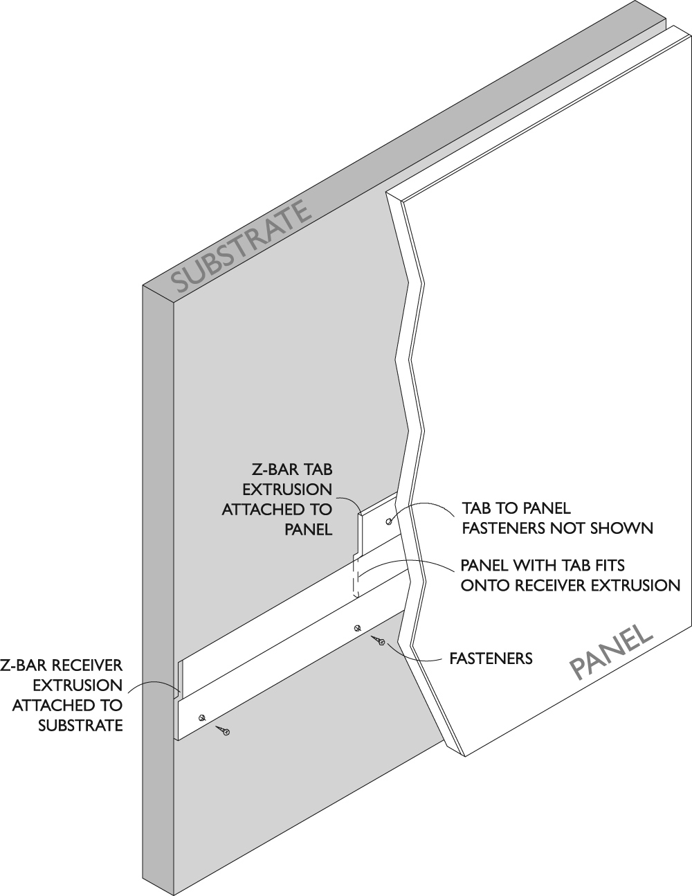
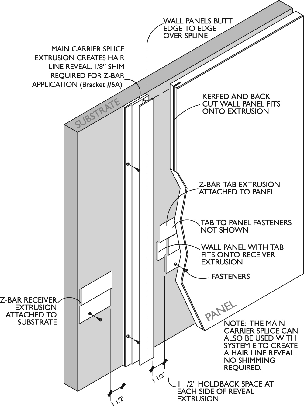
Gage Z-Bar System Detail (not to scale)
SYSTEM “Z” INSTALLATION WITH “THINLINE” PANEL SYSTEM OPTION
8. The main carrier splice extrusion when used in conjunction with the Z-bar installation methods requires basically no modifications to the procedures outlined above. The use of the main carrier splice requires the side of the intersection edge to be kerfed 0.500 inches deep using a 0.060 slotting cutter. The MDF also needs to be back cut .060 inches on each panel side (See below drawing). Refer to the specification section to see if this operation was done as a factory provided procedure. This installation procedure may require the use of a 0.125 inch shim to make for a flush finish surface end result while at the same time securing the main carrier splice securely to the underlying substrate. Refer to the specification and drawings to see if a ”hairline” end result is required. Refer to the drawing below for general installation configuration.