- Provide a smooth, straight, solid and clean substrate. Correct any defects prior to commencement of installation.
- Refer to the drawings (approved shop drawings if required) for correct panel location and layout. Pay particular attention to location of field cut panels. Verify treatment for all termination edges, inside and outside corners (if any), and required cutouts (if any). Coordinate panel surface configuration to determine starting point of perimeter trim, inside and outside corner trim (if any), and panel installation succession. If the drawings are inconsistent or incomplete, contact the factory or specifier for further assistance.
- Make all required cutouts prior to application. Coordinate placement of cutouts with placement of extrusions.
- Notch the vertical edge “J” trim to allow for a tight butt-joint installation of the horizontal main runners. Notch the horizontal edge “J” trim to allow for a tight butt-joint installation of the vertical cross runners. Refer to the drawings and specifications for notching requirements.
- Starting from the left vertical edge of the substrate as looking at the substrate, set the “J” trim to the substrate true to vertical orientation using #8 x 1½ inch flathead torx screws. Space fasteners at a maximum of 16 inches on center. Countersink fastener heads so the fastener flushes out with the “J” trim recessed surface.
- Starting from the bottom edge of the substrate as looking at the substrate, set the “J” trim to the substrate true to the horizontal orientation using #8 x 1½ inch flathead torx screws. Space fasteners at a maximum of 16 inches on center. Countersink fastener heads so the fastener flushes out with the “J” trim recessed base surface.
- Once a true 90° corner has been established, squarely set the first panel into place so that the “J” trim panel-anchoring spline fully engages the kerf in the panel edges.
- Set the first vertical cross runner so that the “J” trim panel anchoring spline fully engages the kerf in the panel edge and fully engages the notch in the bottom “J” trim for a tight butt joint. Fasteners shall only occur on the right side recess of the base.
- Squarely set the next panel into place so that the “J” trim panel-anchoring spline fully engages the kerf in the panel edges.
- Set the next vertical cross runner so that the “J” trim panel anchoring spline fully engages the kerf in the panel edge and fully engages the notch in the bottom “J” trim for a tight butt joint.
- Continue the process until the opposite right vertical edge of the bottom row of the substrate is reached.
- Set the horizontal main runner so that the main runner anchoring spline fully engages the kerf in the panel edges and fully engages the notch in the side “J” trim and vertical cross runners for tight butt joints. Set the main runner to the substrate using #8 x 1½ inch flathead torx screws. Space fasteners at a maximum of 16 inches on center. Countersink fastener heads so the fastener flushes out with the main runner recessed base surface. Fasteners shall only occur on the top recess of the main runner base.
- Repeat Items “7” through “12” above until the top edge of the substrate is ready for installation of the top “J” trim. Set the top “J” trim so that the “J” trim anchoring spline fully engages the kerf in the panel edges and fully engages the notch in the side “J” trim for a tight butt joint. Set the main runner to the substrate using construction adhesive. Remove all traces of excess adhesive immediately.
- Set the opposite vertical side “J” trim so that the “J” trim anchoring spline fully engages the kerf in the panel edges and fully engages the notch in the side main runners for a series of tight butt joints. Set the “J” trim to the substrate using construction adhesive. Remove all traces of excess adhesive immediately.
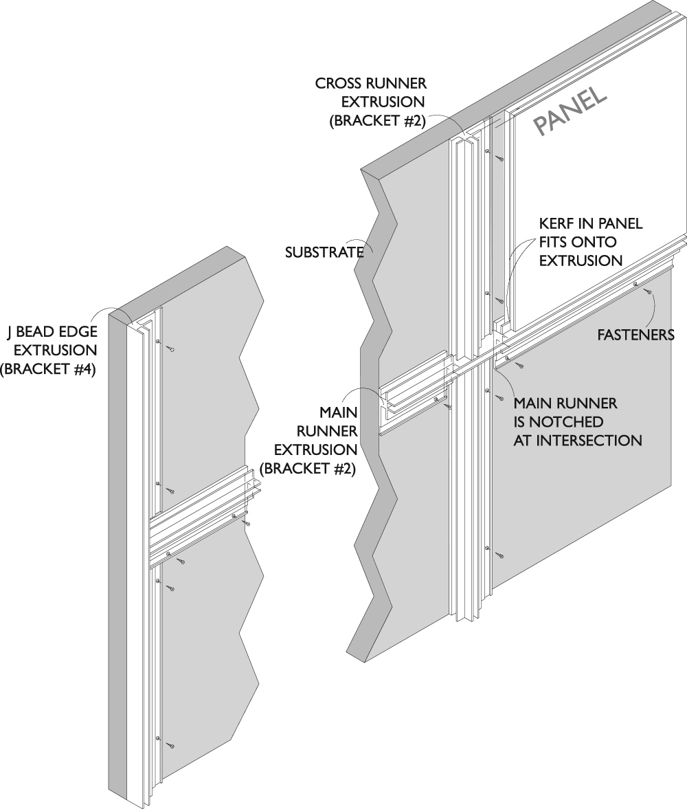
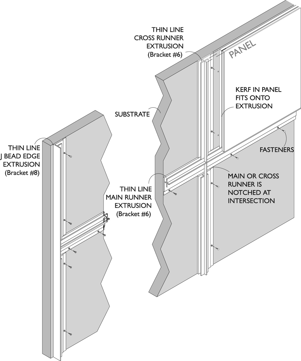
GVS Flat Wall Panel Detail (not to scale)
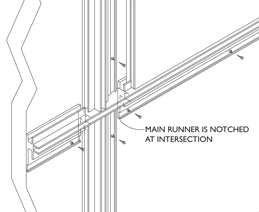
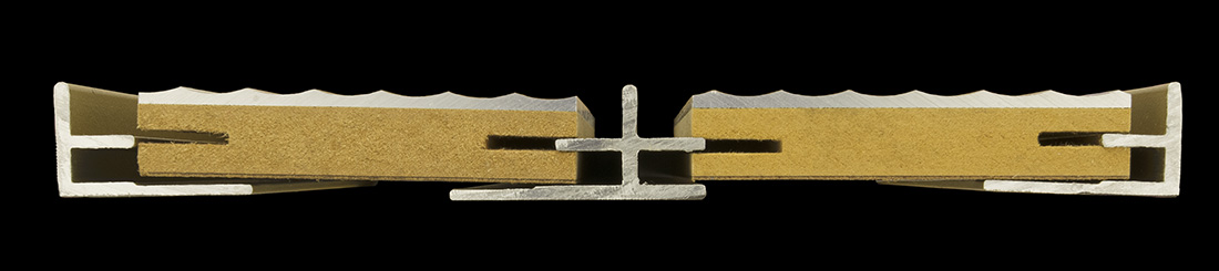
NOTE: Below is an exploded view of the intersection of the cross runners with the main runner. If properly notched, the joint at the intersection should be hairline in nature. If factory notching is specified, this end result is readily achieved.
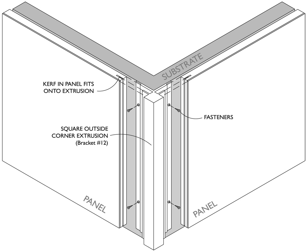
15. The inside and outside corners are one-piece extrusions. Depending upon the panel surface configuration, the starting point of the installation may occur at an inside or outside corner. Panel surface configuration may allow the placement of fasteners along one leg of the base of the corner extrusion only. This is an acceptable method of installation. Set the inside and outside corner trim to the substrate using #8 x 1½ inch flathead torx screws in a similar fashion to the installation of the vertical cross runners. Space fasteners at a maximum of 16 inches on center. Countersink fastener heads so the fastener flushes out with the corner trim recessed base surface. Contact the factory for further assistance.
16. Upon completion of the installation remove all debris caused by this installation. Carefully clean all surfaces with clear water and soap. If stains persist, consult with the factory.
17. Where panel size requires the use of vertical main runners and no cross runners, ignore the instructions regarding cross runner installation.
18. Place protective streamers across the surface and leave in place until the entire Project has been completed.
19. If panel replacement is required, reverse steps “7” through “15” above.

GVS Outside Corner Detail (not to scale)
SYSTEM “E” INSTALLATION WITH “THINLINE” PANEL SYSTEM OPTION
20. The “Thinline” Option extrusion when used in conjunction with the System “E” installation method requires basically no modifications to the procedures outlined above. The use of the “Thinline” extrusions requires the back of the intersection edge of the “hairline” butt joints are required to be kerfed 0.500 inches deep using a 0.060 3-wing slotting cutter. The outside corner requires the intersecting side to be kerfed 0.5000 inches deep using a 0.090 slotting cutter. Refer to the specification section to see if this operation was done as a factory provided procedure. Refer to the specification and drawings to see if a “thinline” or “hairline” end result is required.
21. The “Thinline” system provides one piece corners. Refer to the drawings below for general installation configuration.
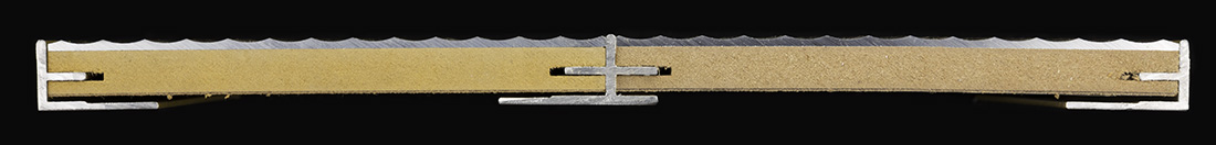
Thinline Flat Wall Panel Detail (not to scale)
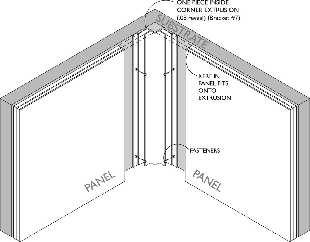
Thinline Inside Corner Detail (not to scale)
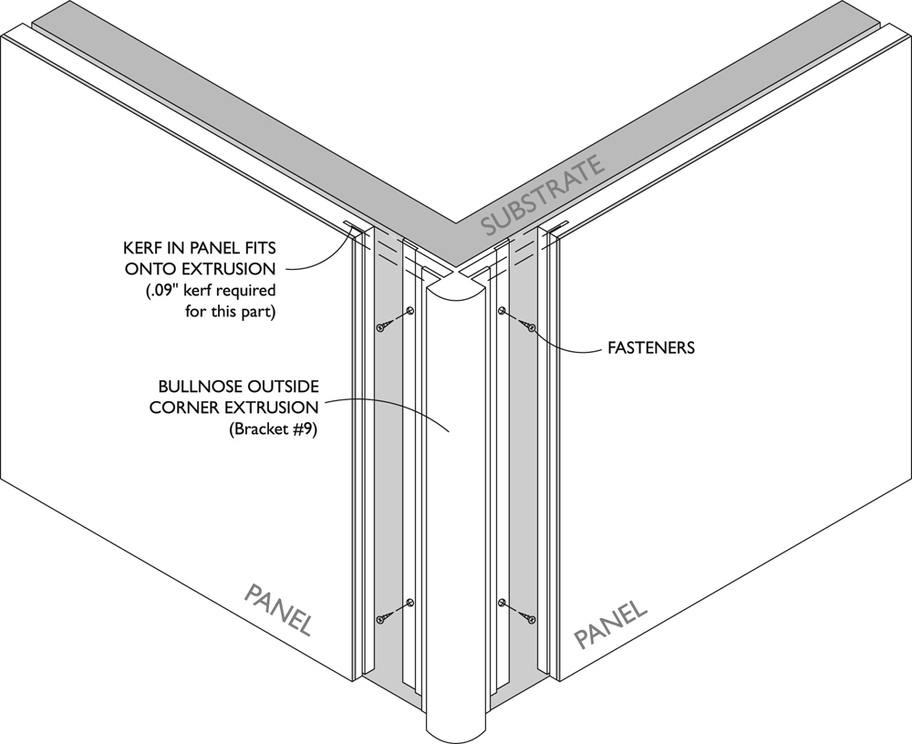
Thinline Bullnose Outside Corner Detail (not to scale)